
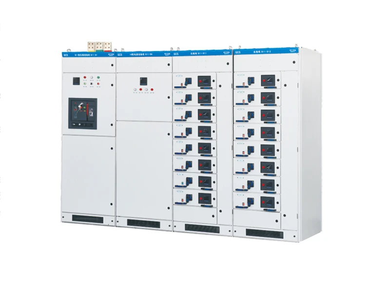
The GCS type low voltage withdrawable Switchgear (hereinafter referred to as“ switchgear”) is designed and developed by our company to meet the requirements of design units and power users. It is in line with the national conditions, has high technical performance indicators,is adaptable to the development needs of the power market, and can compete with existing imported products. The product is widely used by power users and is suitable for distribution systems in industries such as power plants, petroleum, chemical, metallurgy, textiles, and high-rise buildings.
It is used in low-voltage complete distribution devices for power generation, distribution, centralized control of motors, and reactive power compensation in systems with a rated frequency of 50 (60) Hz, a rated working voltage of 380V (400V), (660V), and a rated current of 6300A and below.
This product complies with the standards GB7251 “Low-voltage Switchgear and control equipment,” JB/T9661 “Low-voltage withdrawable switchgear,” IEC60349 “Low-voltage Switchgear and control equipment.’

Ambient Condition
Ambient air temperature: -15°C to +40°C, the daily average temperature should not exceed +35°C. If exceeded, the capacity should be derated based on actual conditions.
Altitude: Not exceeding 2500m.
Relative humidity: Not exceeding 50% at the highest temperature of +40°C. Allow higher relative humidity at lower temperatures,
such as 90% at +20°C. Consider the potential impact of temperature changes leading to condensation.
Installation tilt: Not exceeding 5 degrees, and the entire cabinet column should be relatively flat (compliant with GBJ232-82 standard).
The switchgear should be installed in places without severe vibration and shocks, and where electrical components are not exposed to corrosive environments. Note: When users have special requirements, they can negotiate with the company for solutions.
Ordering Information (Specify when placing an order)
1. Main circuit scheme number, purpose, single-line system diagram, arrangement diagram, and layout plan of the distribution room.
2. Auxiliary circuit wiring diagram, terminal arrangement diagram.
3. Model, specifications, and quantity of electrical components inside the switchgear.
4. Requirements for control, measurement, and protection functions of the switchgear, as well as other interlocking and automatic devices.
5. If busbar bridging connections are needed between switchgear or incoming cabinets, provide specific requirements such as the rated current, span, height above ground, etc.
6. Specify types and quantities of accessories and spare parts.
7. If the switchgear is used in special environmental conditions, provide detailed information when placing the order.
Auxiliary Circuit Schemes:
The auxiliary circuit diagrams for GCS comprise 120 schemes, divided into two volumes – the upper volume, “AC Operation Part,” consists of 63 schemes, and the lower volume, “DC Operation Part,” consists of 57 schemes. The DC operation part is mainly used for low-voltage plant systems in power plants and substations. It is suitable for systems with capacities of 200MW and below and 300MW and above, working (standby) power supply incoming lines, power supply feeders, and general control methods for motor feeders.
The AC operation part’s auxiliary schemes are primarily used in low-voltage systems in substations of factories, mines, enterprises, and high-rise buildings. There are six combination schemes suitable for dual-power operation control, equipped with operation electrical interlock, standby switching, and other control circuits that can be directly adopted in engineering design. The DC control power supply is 220V or 110V, and the AC control power supply is 380V or 220V. It is a complete cabinet composed of drawer units. The 220V control power supply is sourced from the public control power supply provided by the dedicated control transformer in this cabinet. The public control power supply uses an ungrounded method to control the transformer, leaving a 24V
power supply for use when weak current signal lights are needed. The installation location of the electricity meter, the method of introducing voltage, and other installation and usage requirements are detailed in the “Compilation Instructions” of the auxiliary circuit diagram.
Busbars:
To enhance busbar thermal stability and improve contact surface temperature rise, TMY-T2 series hard copper bars are used. The copper bar surface undergoes advanced oxidation-resistant treatment.
a. Horizontal Busbar:
Placed in the rear busbar compartment, arranged in dual layers for 2500A and above, and single-layer for 2500A and below. Each phase consists of 4 or 2 busbars, significantly increasing busbar short-circuit strength.
b. Vertical Busbar:
The vertical busbar for drawers uses “L”-shaped tin-plated hard copper busbars with specifications (height x thickness) + (bottom x thickness) rated at 1000A (50*5)+(30*5).