
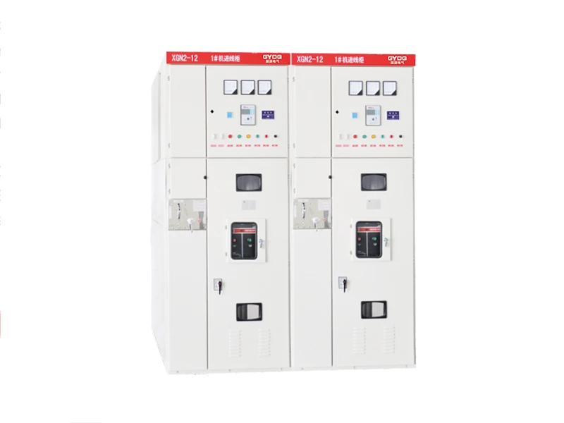
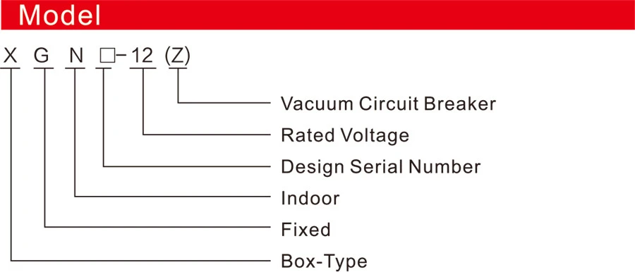
XGN口- 12(Z) Fixed Metal-clad Switchgear (referred to as “switchgear”) is suitable for rated voltages of 3.6~12kV, 50Hz, and rated currents of 630A~3150A three-phase AC single bus, double bus, and single bus with bypass systems, serving the purpose of receiving and distributing electrical energy. It can meet the requirements of various types of power plants, substations, and industrial enterprises.
This product complies with the national standards GB3906 “3~35kV AC Metal-Enclosed Switchgear,” IEC62271-200 ‘ AC Metal- Enclosed Switchgear and Control Equipment,” and DU/T402, DUT404 standards, achieving the “Five Protections” interlocking requirements.
Ambient Condition
Surrounding air temperature:-15°C to +40°C
Altitude: 2500m and below.
Humidity conditions: Daily average not greater than 95%,average vapor pressure not exceeding 2.2kPa; monthly average not greater than 90%,monthly average vapor pressure not exceeding 1 .8kPa. Seismic intensity: Not exceeding 8 degrees.
No obvious pollution, such as corrosive or combustible gases
Note: Consultation with the company is required for special requirements.
Ordering Information (Must be specified when ordering)
1. Main circuit scheme number, purpose, single-line system diagram, arrangement diagram, and layout diagram of the distribution room.
2. Auxiliary circuit wiring diagram, terminal arrangement diagram.
3. Models, specifications, and quantities of electrical components inside the switchgear.
4. Requirements for control, measurement, and protection functions of the switchgear, as well as other interlocking and automatic device requirements.
5. If busbar bridges are required between switchgear or incoming cabinets, provide specific requirements such as the rated current, span, height above ground, etc., of the busbar bridge.
6. When accessories or spare parts are needed, specify the type and quantity.
7. If the switchgear is used in special environmental conditions, provide detailed information when ordering.
Structural Features
Power-On Operation (Maintenance– Run):
1. After completing maintenance, close the rear door, remove the key, and close the front door.
2. Move the small handle from the “Maintenance” position to the “Disconnection Lock” position. The front door is now locked, and
the circuit breaker cannot close.
3. Insert the operating handle into the grounding switch operation hole, pull down, and move to the disconnection position.
4. Remove the handle, insert it into the upper isolating switch operation hole, push up, and move to the upper connection position.
5. Remove the handle, insert it into the lower isolating switch operation hole, push up, and move to the lower connection position.
6. Remove the handle, move the small handle to the working position, and now the circuit breaker can be closed.
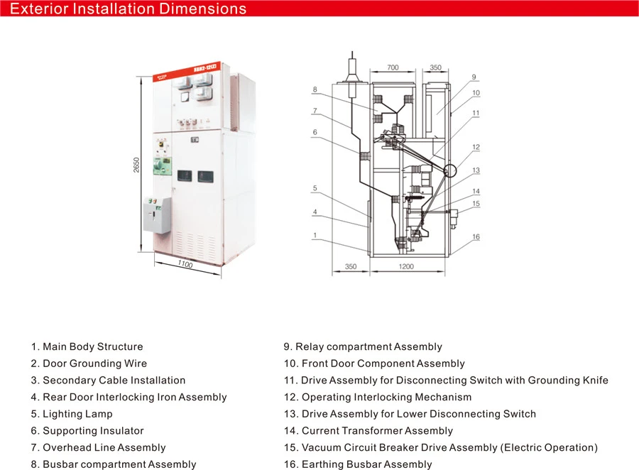
Product Dimensions and Structural Diagram (Refer to Figures 1,2, 3):
(Provide a detailed description or attach diagrams for a visual representation.)